
Multiplexing is accomplished by utilizing a device known as a multiplexer (MUX).
Multiplexing in computer networks combines n input lines to produce a single output line. Multiplexing is done in a many-to-one fashion, with n input lines and one output line.
Demultiplexing is accomplished at the receiving end by employing a device known as a demultiplexer (DEMUX). DEMUX divides a signal into its constituent components (one input and n outputs). As a result, demultiplexing follows the one-to-many technique.
Multiplexing in computers is a method of combining and transmitting several data streams across a single medium. It is the process of merging data streams, and the gear used for multiplexing is known as a multiplexer.
History of Multiplexing
- The multiplexing technique is widely used in telecommunications, in which several telephone calls are carried through a single wire.
- The multiplexing computer originated in telegraphy in the early 1870s and is now widely used in communication.
- George Owen Squier developed the telephone carrier multiplexing in 1910.
What is multiplexing in a computer?
Multiplexing is a technique used to combine and send the multiple data streams over a single medium. The process of combining the data streams is known as multiplexing in computers, and hardware used for multiplexing is known as a multiplexer.
Multiplexing is achieved by using a device called a multiplexer (MUX) that combines n input lines to generate a single output line. Multiplexing in a computer follows many-to-one, i.e., n input lines and one output line.
Demultiplexing in computer achieved by using a device called Demultiplexer (DEMUX) available at the receiving end. DEMUX separates a signal into its component signals (one input and n outputs). Therefore, we can say that demultiplexing follows the one-to-many approach.
Why multiplexing in a computer?
- The transmission medium is used to send the signal from sender to receiver. The medium can only have one signal at a time.
- If there are multiple signals to share one medium, then the medium must be divided in such a way that each signal is given some portion of the available bandwidth. For example, if there are 10 signals and the bandwidth of the medium is 100 units, then the 10 units are shared by each signal.
- When multiple signals share the common medium, there is a possibility of collision. Multiplexing in computer concepts is used to avoid such collisions.
- Transmission services are very expensive.
The concept of multiplexing is that ‘n’ input lines are transmitted through a multiplexer, and the multiplexer combines the signals to form a composite signal.
- The composite signal is passed through a demultiplexer, and the demultiplexer separates a signal from component signals and transfers them to their respective destinations.
Advantages of Multiplexing in a Computer:
- More than one signal can be sent over a single medium.
- The bandwidth of a medium can be utilized effectively.
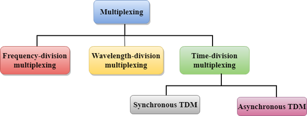
Multiplexing Techniques
Multiplexing techniques can be classified as:
Need for Multiplexing:
- The signal is sent from sender to receiver via the transmission medium. There can only be one signal on the medium at any given moment.
- If several signals must share a single media, the medium must be split so that each signal receives a fraction of the available bandwidth.
- When numerous signals use the same medium, there is a chance that they will collide. To avoid such collisions, the concept of multiplexing is utilized.
- Transmission services are exorbitantly priced.
Concept of Multiplexing:
- The ‘n’ input lines are routed via a multiplexer, which combines the signals to create a composite signal.
- The composite signal is routed to a multiplexer, which divides a signal into component signals and routes them to their appropriate destinations.
Frequency-division Multiplexing (FDM)
- It is an analog technique.
- Frequency Division Multiplexing in computers is a technique in which the available bandwidth of a single transmission medium is subdivided into several channels.
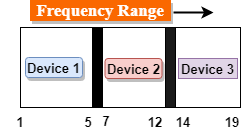
- In the above diagram, a single transmission medium is subdivided into several frequency channels, and each frequency channel is given to different devices. Device 1 has a frequency channel ranging from 1 to 5.
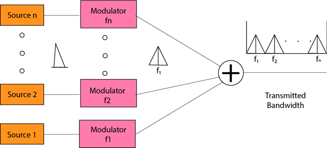
- The input signals are translated into frequency bands by using modulation techniques, and they are combined by a multiplexer to form a composite signal.
- The main aim of the FDM is to subdivide the available bandwidth into different frequency channels and allocate them to different devices.
- Using the modulation technique, the input signals are transmitted into frequency bands and then combined to form a composite signal.
- The carriers that are used for modulating the signals are known as sub-carriers. They are represented as f1, f2, …, fn.
- FDM is mainly used in radio broadcasts and TV networks.
Advantages of FDM:
- FDM is used for analog signals.
- The FDM process is very simple and easy to modulate.
- A large number of signals can be sent through an FDM simultaneously.
- It does not require any synchronization between sender and receiver.
Disadvantages of FDM:
- The FDM technique is used only when low-speed channels are required.
- It suffers from the problem of crosstalk.
- A large number of modulators are required.
- It requires a high-bandwidth channel.
Applications of FDM:
- FDM is commonly used in TV networks.
- It is used in FM and AM broadcasting. Each FM radio station has different frequencies, and they are multiplexed to form a composite signal. The multiplexed signal is transmitted in the airCode Division Multiplexing (CDM):
- Code Division Multiplexing in computer allows several data signals to be delivered over a single frequency.
- FDM divides the frequency into smaller channels, but CDM allows users to use the entire bandwidth and broadcast signals at all times using a unique code. To disseminate signals, CDM employs orthogonal coding.
- Each station is given a unique code, known as a chip. Signals move independently with these codes over the whole bandwidth. The chip-code signal that the receiver must receive is known in advance.
Asynchronous TDM
- An asynchronous TDM is also known as a statistical TDM.
- An asynchronous TDM is a technique in which time slots are not fixed, as in the case of synchronous TDM. Time slots are allocated to only those devices that have the data to send. Therefore, we can say that asynchronous time division multiplexing in computers transmits only the data from active workstations.
- An asynchronous TDM technique dynamically allocates the time slots to the devices.
- In asynchronous TDM, the total speed of the input lines can be greater than the capacity of the channel.
- Asynchronous Time Division multiplexor accepts the incoming data streams and creates a frame that contains only data with no empty slots.
- In asynchronous TDM, each slot contains an address part that identifies the source of the data.

- The difference between Asynchronous TDM and Synchronous TDM is that many slots in Synchronous TDM are unutilized, but in Asynchronous TDM, slots are fully utilized. This leads to a smaller transmission time and efficient utilization of the capacity of the channel.
- In synchronous TDM, if there are n sending devices, then there are n time slots. In asynchronous TDM, if there are n sending devices, then there are m time slots where m is less than n (m<n).
- The number of slots in a frame depends on the statistical analysis of the number of input lines.
Concept Of Asynchronous TDM
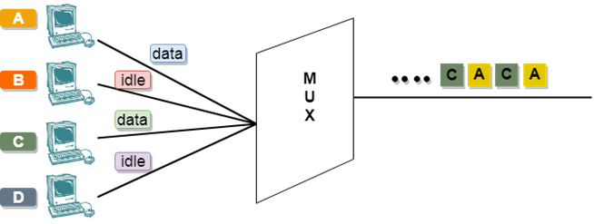
In the above diagram, there are 4 devices, but only two devices are sending the data, i.e., A and C. Therefore, the data of A and C are only transmitted through the transmission line.
The frame of the above diagram can be represented as:
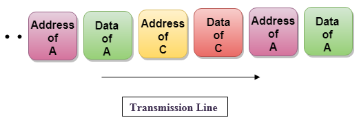
The above figure shows that the data part contains the address to determine the source of the data.